Servo Motor Basics with Arduino
Learn how to connect and control servo motors with your Arduino board.
The Servo Library is a great library for controlling servo motors. In this article, you will find two easy examples that can be used by any Arduino board.
The first example controls the position of an RC (hobby) servo motor with your Arduino and a potentiometer. The second example sweeps the shaft of an RC servo motor back and forth across 180 degrees.
You can also visit the Servo GitHub repository to learn more about this library.
Hardware Required
- Arduino Board
- Servo Motor
- 10k ohm potentiometer
- hook-up wires
- capacitors
- power supply
Powering Servo Motors
Servo motors have different power requirements depending on their size and the workload they are experiencing. A common servo motor such as the Feetech Mini Servo Motor requires between 4.8 - 6 V at 5 – 6 mA when idle. It doesn't take very much energy to stand still.
But as soon as the motor starts moving, it starts using more energy, and it gets that energy by pulling more current from the power source.
If it experiences heavier loads such as added weight or an object blocking its movement , it naturally needs to use even more energy to move the obstacle, and as a result the current consumption increases. The current consumption of the motor linked above can reach up to 800 mA.
This high current-draw is generally not safe to draw from an Arduino board. To avoid damaging our board we need to power the servo motor through an external power supply. Choosing the correct power supply depends on the servo motor you are using, so always check the specifications. Pay especially close attention to the:
- operating voltage range
- idle current - consumption when not moving
- running current - consumption when moving freely
- stall current - consumption under max load or when blocked
To power a 4.8 - 6 V servo you could use a 5 V 1 A AC Adapter, cut the cable, and connect the wires to the servo using e.g. a breadboard.
Note that USB wall chargers are limited to 500 mA (USB 2.0) or 900 mA (USB 3.0).
If your project needs to move around freely without being attached to a power outlet you can also choose batteries to power the servo. If you need 5 V exactly you can use two 18650 Li-Ion batteries together with a step-down converter.
A step-down converter is needed because 18650 Li-Ion batteries will give you around 7.4 V. The max current depends on the specific battery but most of them are designed to output above 1A which is enough to power our small servo.
If you are using bigger or more servos make sure to check your power requirements accordingly.
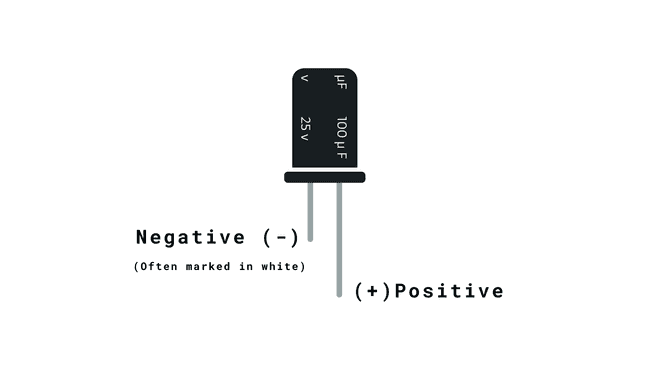
Capacitors are recommended for powering servo motors. They help stabilize the power supply, minimize voltage drops, and reduce electrical noise. The specific capacitor values may vary based on the servo motor's requirements, but including them is good practice for better performance and reliability.
When using a Feetech Mini Servo Motor we recommend using a 100 µF capacitor.

Because some capacitors are polarised (meaning that they have a direction), you may need to be careful with how you connect them to your circuit. Make sure to connect them correctly by checking for markings such as a white stripe, a '+' symbol, or a longer lead. If your capacitor has these, match the indicators of the capacitor with your circuit (pay attention to the + and - signs), and be careful not to exceed the voltage limits. This precaution helps prevent issues like leaks or damage that could harm your circuit.
You can read more about capacitors here.
Circuit
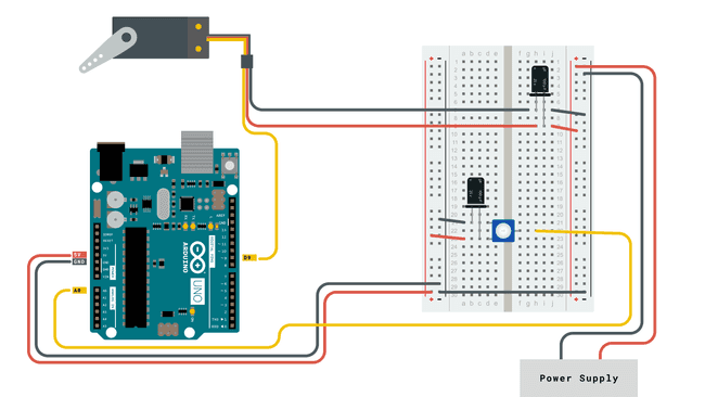
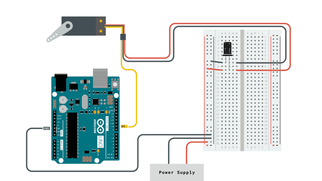
Servo motors have three wires: power, ground, and signal. The power wire is typically red, and should be connected to positive pole (+) of your power source. The ground wire is typically black or brown and should be connected to the negative pole (-) of your power source.
The signal pin is typically yellow or orange and should be connected to PWM pin on the board. In these examples, it is pin number 9.
Knob Circuit
For the Knob example, wire the potentiometer so that its two outer pins are connected to power (+5V) and ground, and its middle pin is connected to
A0
Sweep Circuit
For the Sweep example, connect the servo motor as shown in the circuit below.

Examples
Knob
Controlling a servo position using a potentiometer (variable resistor).
1#include <Servo.h>2
3Servo myservo; // create servo object to control a servo4
5int potpin = 0; // analog pin used to connect the potentiometer6int val; // variable to read the value from the analog pin7
8void setup() {9 myservo.attach(9); // attaches the servo on pin 9 to the servo object10}11
12void loop() {13 val = analogRead(potpin); // reads the value of the potentiometer (value between 0 and 1023)14 val = map(val, 0, 1023, 0, 180); // scale it to use it with the servo (value between 0 and 180)15 myservo.write(val); // sets the servo position according to the scaled value16 delay(15); // waits for the servo to get there17}Sweep
Sweeps the shaft of a RC servo motor back and forth across 180 degrees.
1#include <Servo.h>2
3Servo myservo; // create servo object to control a servo4// twelve servo objects can be created on most boards5
6int pos = 0; // variable to store the servo position7
8void setup() {9 myservo.attach(9); // attaches the servo on pin 9 to the servo object10}11
12void loop() {13 for (pos = 0; pos <= 180; pos += 1) { // goes from 0 degrees to 180 degrees14 // in steps of 1 degree15 myservo.write(pos); // tell servo to go to position in variable 'pos'16 delay(15); // waits 15ms for the servo to reach the position17 }18 for (pos = 180; pos >= 0; pos -= 1) { // goes from 180 degrees to 0 degrees19 myservo.write(pos); // tell servo to go to position in variable 'pos'20 delay(15); // waits 15ms for the servo to reach the position21 }22}Suggest changes
The content on docs.arduino.cc is facilitated through a public GitHub repository. If you see anything wrong, you can edit this page here.
License
The Arduino documentation is licensed under the Creative Commons Attribution-Share Alike 4.0 license.