Receive a Voice Call with MKR GSM 1400
Learn how to setup your board to accept incoming voice calls.
Introduction
In this tutorial, we will use the ReceiveVoiceCall example from the MKRGSM library. It will show how to set up our MKR GSM 1400 board to handle incoming calls, and uses the Serial Monitor to provide information regarding the call.
Goals
The goals of this project are:
- Set up the MKR GSM 1400 board to receive voice calls.
- Create a function that ends the call.
Hardware & Software Needed
- Arduino IDE (online or offline).
- MKRGSM library installed.
- Arduino MKR GSM 1400.
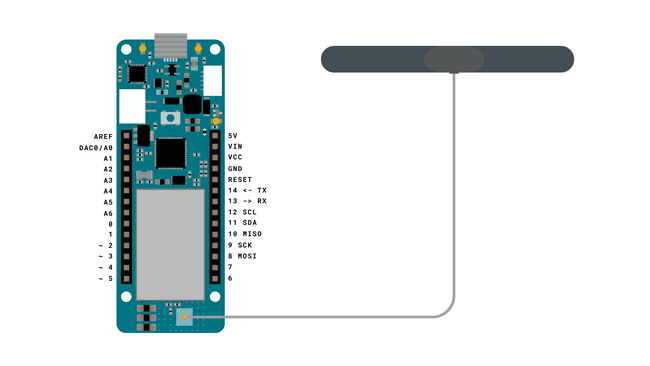
- Antenna.
- SIM card from an operator in your country.
Voice Calls
As the MKR GSM 1400 board is capable of connecting to the GSM network, we also have the possibility to place and receive calls. This feature can be incredibly useful for remotely controlling devices, particularly those in rural / inaccessible areas.
As most of us know, the past decades has seen a massive increase in the use of smart phones, and with it, the infrastructure for cellular communication has developed significantly. This means more coverage and more reliable services, and an ideal platform to use for IoT projects.
Useful Scenarios
Some useful scenarios for using the voice call feature includes:
Simple feedback - perhaps the simplest way of using the voice call feature is simply by placing a call to the MKR GSM 1400 board to check if the device is "alive". If we establish a call with the device, we can confirm that it is functioning, but if it goes to voice mail, something is not working!
Trigger something - whenever a call comes in, we can configure a sketch to for example execute a function.
Retrieve data - we can also configure a sketch that, when a call comes in, we can do a reading on X amount of sensors, and send it back to the callers number using the GSM_SMS class.
Circuit

Creating the Program
We will now get to the programming part of this tutorial.
1. First, let's make sure we have the drivers installed. If we are using the Web Editor, we do not need to install anything. If we are using an offline editor, we need to install it manually. This can be done by navigating to Tools > Board > Board Manager.... Here we need to look for the Arduino SAMD boards (32-bits Arm® Cortex®-M0+) and install it.
2. Now, we need to install the libraries needed. If we are using the Web Editor, there is no need to install anything. If we are using an offline editor, simply go to Tools > Manage libraries.., and search for MKRGSM and install it.
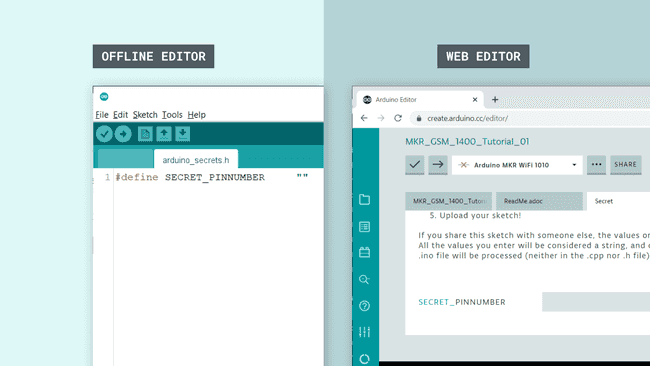
3. We can now go to File > Examples > MKRGSM > ReceiveVoiceCall in the editor. This will open a new window, which has a sketch tab, but also a header file, called
arduino_secrets.h
Inside this file, we need to enter our pin number between the " ".
1#define SECRET_PINNUMBER "" //enter pin code between " "The pin number is often 1234 or 0000, but for more information, check the SIM plan that you bought.
4. We can now take a look at some of the core functions of this sketch:
- base class for all GSM functions.GSM gsmAccess
- base class for GSM voice call functions.GSMVoiceCall vcs
- checks if there's a call, and returns:vcs.getvoiceCallStatus()
(no call),IDLE_CALL
(a call is incoming) orRECEIVINGCALL
(a call is happening).TALKING
- retrieves the number of the caller and store invcs.retrieveCallingNumber( , 20)
variable.numtel
- used to answer incoming calls.vcs.answerCall()
- used to hang up on current calls.vcs.hangCall()
The sketch can also be found in the snippet below. Upload the sketch to the board.
1// Include the GSM library2#include <MKRGSM.h>3
4#include "arduino_secrets.h" 5// Please enter your sensitive data in the Secret tab or arduino_secrets.h6// PIN Number7const char PINNUMBER[] = SECRET_PINNUMBER;8
9// initialize the library instance10GSM gsmAccess;11GSMVoiceCall vcs;12
13// Array to hold the number for the incoming call14char numtel[20];15
16void setup() {17 // initialize serial communications and wait for port to open:18 Serial.begin(9600);19 while (!Serial) {20 ; // wait for serial port to connect. Needed for native USB port only21 }22
23 Serial.println("Receive Voice Call");24
25 // connection state26 bool connected = false;27
28 // Start GSM shield29 // If your SIM has PIN, pass it as a parameter of begin() in quotes30 while (!connected) {31 if (gsmAccess.begin(PINNUMBER) == GSM_READY) {32 connected = true;33 } else {34 Serial.println("Not connected");35 delay(1000);36 }37 }38
39 // This makes sure the modem correctly reports incoming events40 vcs.hangCall();41
42 Serial.println("Waiting for a call");43}44
45void loop() {46 // Check the status of the voice call47 switch (vcs.getvoiceCallStatus()) {48 case IDLE_CALL: // Nothing is happening49
50 break;51
52 case RECEIVINGCALL: // Yes! Someone is calling us53
54 Serial.println("RECEIVING CALL");55
56 // Retrieve the calling number57 vcs.retrieveCallingNumber(numtel, 20);58
59 // Print the calling number60 Serial.print("Number:");61 Serial.println(numtel);62
63 // Answer the call, establish the call64 vcs.answerCall();65 break;66
67 case TALKING: // In this case the call would be established68
69 Serial.println("TALKING. Press enter to hang up.");70 while (Serial.read() != '\n') {71 delay(100);72 }73 vcs.hangCall();74 Serial.println("Hanging up and waiting for the next call.");75 break;76 }77 delay(1000);78}Testing It Out
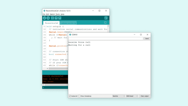
After the code has successfully uploaded, open the Serial Monitor. There should now be two messages printed, one after the other:
"Receive Voice Call""Waiting for a call"
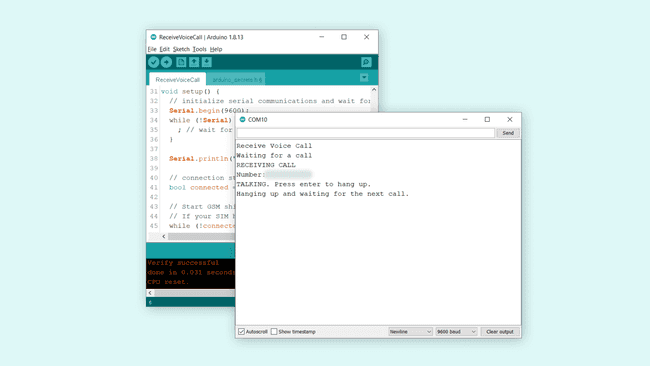
Now, all we need to do is placing a call to the MKR GSM 1400 board. Simply check the phone number of the SIM card that you connected to your board, and call it. When the call is received by the board, it automatically answers it, and prints the caller's number in the Serial Monitor, as shown in the image below.

Now, in the Serial Monitor, we have the option to hang up on the call by simply pressing enter. This is a configuration in the sketch example. When we press enter, the text
"Hanging up and waiting for the next call."Note: This setup is not designed to support a "real" phone call between two devices. There is no speaker or microphone component on the MKR 1400 GSM board, and no function in the MKRGSM library supports this feature.
Troubleshoot
If the code is not working, there are some common issues we can troubleshoot:
- We have not installed the MKRGSM library.
- We have entered the wrong pin number.
- We are out of coverage (no signal).
- We have entered the wrong number.
- SIM card may not be activated.
Conclusion
In this tutorial, we went through the ReceiveVoiceCall example that allows us to receive voice calls on the MKR GSM 1400 board. This feature can be easily configured to handle tasks on the board, such as executing functions, and is relatively easy to setup in terms of hardware and software.
Feel free to explore the MKRGSM library further, and try out some of the many cool functions in this library.
Suggest changes
The content on docs.arduino.cc is facilitated through a public GitHub repository. If you see anything wrong, you can edit this page here.
License
The Arduino documentation is licensed under the Creative Commons Attribution-Share Alike 4.0 license.